Wooden frame joints with DOMINO

Description
With the small DOMINO router, very small dowels can be used even for furniture joints, making it possible to machine very small spindles or narrow frame rails.
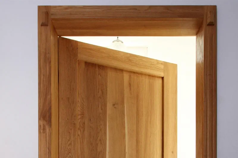
The DOMINO XL joining machine, on the other hand, can be used to create stable wooden frames in the same way, such as for beds, tables or internal doors. Thanks to the larger routing depth, the DOMINO XL joining machine is also suitable for pinned joints. Some of these connection options are demonstrated in the following examples.
Tools/accessories


Procedure
-
In this example, we are processing 5 x 30 mm dowels. Set the routing depth to 15 mm for this.

-
Select the routing height based on the workpiece; in this example, the frame is 20 mm thick. Set the routing height on the DF 500 to 20 mm in this case. The width of the frame in this example is 60 mm.

-
We are using two dowels per corner connector for maximum stability. Place the routing machine on the mitre cross section and carefully work with the stop catch at the side against the tip of the mitre. Route the first hole with precision.

-
For the second routed hole, either mark out the position or run the machine flush along the outside tip of the mitre. This routed hole can either be precisely routed like the first hole – which increases the stability of the joint but requires more precision. Or it can be routed with clearance – but then you must use a sufficient amount of glue for the joint. Use this method to route the holes in all four frame rails.

-
Insert the dowels in the wooden frame joint from one side, using a sufficient amount of glue.

-
Then build the frame rail and brace it with clamps, for example.


Procedure
-
When connecting frame rails without mitring, i.e. butted wooden frame joints, proceed largely as in the first example. This example shows another option for using the DOMINO joining machine on the workpiece.

-
Set the routing height to match the thickness of your workpiece. For the routing depth, select half the dowel length. Route the holes either by using the correct hole width for both for extreme precision fit or by routing the second hole with clearance.

-
The routed holes can be set not only by marking them or using the stop system, but also with the scale in the viewing window – in this example, 15 mm from the outside edge. For this option, place the scale with the 15 mm marking at the edge of the workpiece.

-
The second routed hole is set here using the stop catch. This method makes it possible to position two dowels next to each other working from just one reference edge.

-
Tip: When using the stop catches, the edge of the workpiece can be seen in the triangular viewing window of the DOMINO joining machine.

-
Use this method to carry out routing for all four frame rails, whereby every second wooden frame rail is routed into the workpiece lengthwise instead of into the front.

-
Then glue the frame rails and brace them with pads and clamps, if necessary.

-
Tip: If the wooden frame rail needs to be rebated or grooved after jointing, the rebating depth must be added in advance when routing the dowel holes, so that the dowel is centred later despite the rebate (which then takes up part of the depth of the dowel hole).


Procedure
-
Use the DOMINO XL for stable wooden frame joints such as for doors, where larger dowels can be processed for even greater stability. In this example, a panel door is created with a pinned internal rebate and additional tenon. The DOMINO joining machines are unique in that you can set the routed holes even after rebating, which would not be possible with a classic drill for conventional dowelling joints, for example, due to the lack of support surface. This pinned joint requires small deviations in the routing depth setting which are explained below.

-
Tip: Due to the pinned joint, the 14 x 140 mm dowel cannot be processed despite the maximum routing depth of 70 mm for the DF 700. The maximum possible standard dowel is therefore the 14 x 100 mm. However, if you wish to make full use of the maximum routing depth and cut the dowel itself to the correct maximum size, you can do so by cutting the dowel to the appropriate length and creating the perfect dowel size yourself.

-
Mark out the required position of the dowel and work using the viewing window. Route into both parts of the workpiece at the maximum routing depth (70 mm each) with the 14 mm router. In the end grain, set both routed holes with the correct hole width – in this case the dowels are later glued and then fit in precisely. The routing height is half of the workpiece thickness (which is 40 mm in this example, so the routing height setting is 20 mm).

-
Route the dowel holes in the stile with a 70 mm routing depth, routing the first hole with precision and the second as an elongated hole with clearance. Carry out the same procedure on the other stiles and rails.

-
Then cut the dowels to fit the ready-made holes. The nominal dowel length in this example is 115 mm: This is calculated by doubling the routing depth of 70 mm = 140 mm and subtracting the pinned joint of 25 mm = 115 mm. Cut the dowel a few millimetres shorter (so that the glue has enough space later), down to 112 mm.

-
Chamfer the cut dowel at the edges using a sanding block. This makes the individual parts much easier to join.

-
Then drive the dowels all the way into the routed holes in the end grain, adding glue to the joint. Join the stiles and rails using fastening clamps and glue the joint. In this way, you can also produce very stable wooden frames with a handheld machine.


-
Our illustrated guides and work results are documented working steps that we have performed in practice. They are individual examples and do not guarantee or promise that users will obtain the same results. The results will depend on the user's experience and skill, as well as the material being used. Illustrated guides do not replace any Festool operating manuals and/or safety instructions. Liability for ensuring that the information, instructions and applications are free from content defects and defects of title, in particular with regard to the absence of defects, correctness, freedom from third party intellectual property rights and copyrights, completeness and fitness for purpose, is excluded. Claims for damages made by the user, regardless of their legal basis, are excluded. These liability exclusions are not applicable if the damage was intentional or caused by gross negligence, or in cases of statutory liability.
We cannot accept liability for damage resulting from defects.↑
