


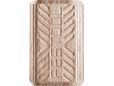


Routing a groove in wood

Description
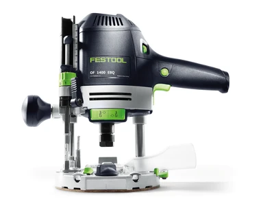
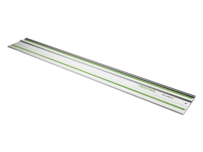
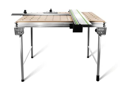
The router and the guide rails, in combination with the multifunction table, make routing a straight groove quick and easy.
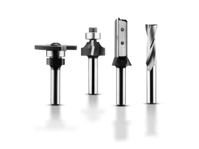
Grooves of varying widths can be routed. Groove cutters of various diameters are available for this task. Typical sizes are between 3 mm and 30 mm.
This illustrated guide shows how to route continuous, non-continuous and inset grooves.
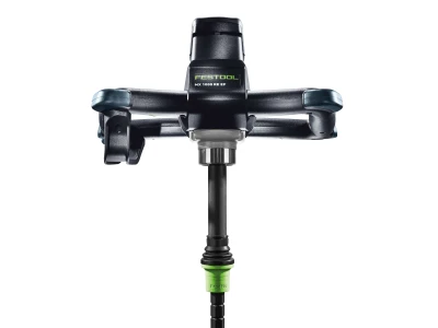
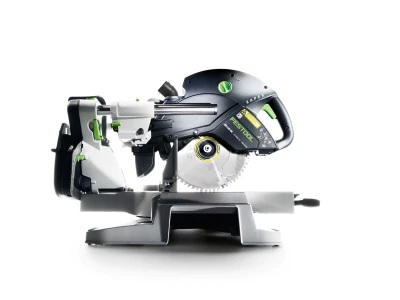
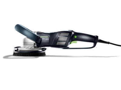
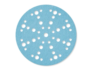
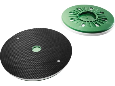
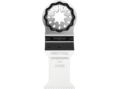
Tools/accessories


Alternative tools/accessories
Depending on the required groove width, any other groove cutter that has a shaft with a diameter of 8 mm can be used. When using larger routers, cutters with a shaft diameter of up to 12 mm can be used.


Preparation/set-up
-
Adjust the guide rail and angle stop to a precise right angle using the Operating Instructions.
Set the guide rail to workpiece thickness.
Workpiece:
Draw the centre line of the groove on the workpiece.
For non-continuous groove:
Mark limiting lines perpendicular to the centre line.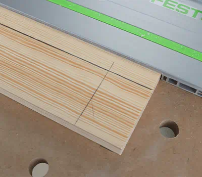
-
The minimum distance x from the centre of the cutter to the edge of the guide rail depends on the cutter diameter and is calculated as follows:
x = cutter diameter in mm/2 + 2 mm
2 mm are added as a tolerance when routing.
For a 12 mm groove cutter, this results in a distance of 8 mm to the guide rail.
The mark on the router table is used to align the machine.
-
Adjusting the router:
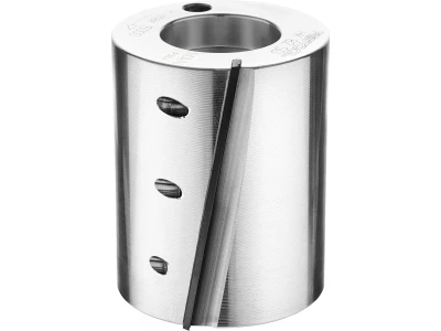
Insert cutter in collet up to the minimum clamping depth (shaft marking) and tighten.
Fit the FS guide rail adapter on the OF.
Place the OF on the guide rail.
Set the desired routing depth. The turret stop can be used to pre-set up to three routing depths.
Set the lateral clearance of the router to the guide rail (see calculation; in the example x = 8 mm with a 12 mm groove cutter).
Align the mark on the router table with the centre line.
Check: The mark should always be on the centre line at the start and end of the groove.
Place the support for the router on the surface of the workpiece and tighten it.
-
For non-continuous or inset grooves, use the guide rail kickback stop.
Move the router to the respective limiting position of the groove and fasten a kickback stop here before starting the routing process.
Set the speed using the table in the Operating Instructions.
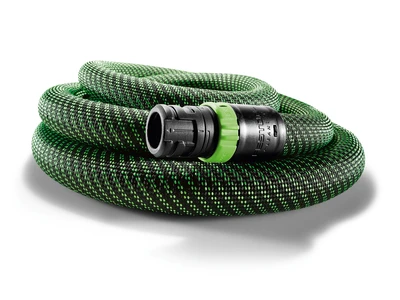
Attach the extractor hose.


Procedure
-
When working with the MFT and with the stop set exactly, the workpiece is positioned against the stop rail and secured and clamped.
Set the router on the rail.
Switch on the router and move it to the pre-set depth stop before the workpiece. For continuous grooves, move it to the correct depth or, for inset grooves, plunge it into the workpiece.Note: The cutter must not be touching the workpiece when the router is switched on.
To rout a groove, guide the router to the set limit or, to rout a continuous groove, guide the router past the edge of the workpiece.
Use a wooden splinter guard to prevent the wood at the end of the workpiece from splitting during routing.
Repeat the procedure until the groove has reached the correct depth. The three routing depths that were pre-set using the turret stop are useful when doing this.

-
Our illustrated guides and work results are documented working steps that we have performed in practice. They are individual examples and do not guarantee or promise that users will obtain the same results. The results will depend on the user's experience and skill, as well as the material being used. Illustrated guides do not replace any Festool operating manuals and/or safety instructions. Liability for ensuring that the information, instructions and applications are free from content defects and defects of title, in particular with regard to the absence of defects, correctness, freedom from third party intellectual property rights and copyrights, completeness and fitness for purpose, is excluded. Claims for damages made by the user, regardless of their legal basis, are excluded. These liability exclusions are not applicable if the damage was intentional or caused by gross negligence, or in cases of statutory liability.
We cannot accept liability for damage resulting from defects.↑
