


Cold frame for balcony and patio

Required materials

- Position 1*: 1x; Back wall length: 900; Width: 380; Thickness: 18; Plywood
- Position 2: 1x; Front; 900 x 279 x 18; Plywood
- Position 3: 2x; Side 540 x 380 x 18; Spruce; Plywood
- Position 4: 1x; Shelf 960 x 130 x 18; Plywood
- Position 5: 2x; Frame pieces, long; 960 x 80 x 18; Plywood
- Position 6: 2x; Frame pieces, short; 350 x 80 x 18; Plywood
- Position 7: 1x; Closure 270 x 60 x 18; Plywood
- Position 8: 4x; Adjustable foot, round; dia. 120 Thickness: 18; Plywood
- Position 9: 8x; Slatted shelf, bottom: 900 x 50 x 20; Larch
- Position 10: 2x; Slatted shelf supports, bottom; 576 x 50 x 20; Larch
- Position 11: 7x; Slatted shelf, top 864 x 50 x 20; Larch
- Position 12: 2x; Slatted shelf supports, top; 5450 x 20 x 20; Larch
- Position 13: 4x; Support block; 150 x 46 x 46; Larch
- Position 14: 2x; Leg, long; 956 x 50/50 x 4; Aluminium bracket
- Position 15: 2x; Leg, short; 862 x 50/50 x 4; Aluminium bracket
- Position 16: 1x; Pane; 840 x 390 x 5; Acrylic glass
- Position 17: 1x; Bolt with ring and chain; Length: 60, dia. 8; Aluminium bar
- Position 18: 1x; Chain for the lid; Length approx. 650; Iron
- Position 19: 3x; Hinge; length 60; stainless steel
- Position 20: 10x; Washers; M6; Plastic
- Position 21: 4x; Knock-in socket; M10; Iron
- Position 22: 4x; Machine screws; length 80; M10; stainless steel
- Position 23: 4x; Nuts; M10; stainless steel
- Position 24: 8x; Washers; dia. 20; M10; stainless steel
* Position in drawing
Construction plan drawing

Details: Scale 1:1
1: Front view
2: Side view
3 & 6: Detail view of height-adjustable foot (Scale 1:1)
4: Interior view 1
5: Interior view 2


Other accessories
- 3.5 mm wood drill bit
- 11 mm drill bit
- Hammer
- Awl
- 2x 17 mm socket wrench
Procedure
-
Step 1
Cut the individual boards and slats to the specified sizes from the material list. Mark the sloping angles on both side pieces (position 3) and use a hand saw with guide rail to cut them out.

-
Step 2
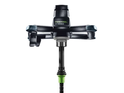
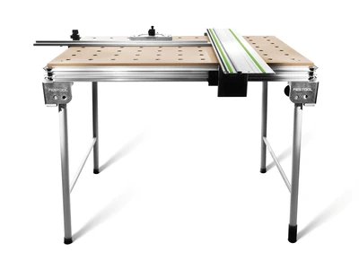
Using the multifunction table shown in the photo, set the stop rail at an angle and fasten the workpiece to the table. You can also use this to cut out the aluminium profiles for the legs.

-
Step 3
You must always use the correct saw blade (universal or aluminium toothed) and reduce the speed. Important: Wear protective goggles to protect your eyes from aluminium shavings.

-
Step 4
Pre-drill the 3.5 mm diameter for the SPAX screws (3.5 x 35) on the front and back walls (positions 1 and 2). Use clamps to fasten together the four boards that are used to make the box, then check the alignment and screw together.

-
Step 5
The front board (position 2) can either be pre-cut on an angle with a circular saw or it can be planed to create the angle. Pre-drill the 3.5 mm holes for the SPAX screws in the shelf (position 4).

-
Step 6
Mark the overhang of the board under the shelf, align the board onto the box and screw them together.

-
Step 7
The four parts needed for the lid are connected using dowels. If possible, use water-resistant wood (oak, sipo wood) for the dowels (8 x 40 mm). Use a simple template when drilling the holes for the dowel connections.

-
Step 8
Mark the positions of the individual frame pieces using the carpenter's triangle marking system. First, drill two 8 mm dowel holes (drill depth = half the dowel length + 1 mm) into each of the short narrow edges of the frame pieces (position 6).

-
Step 9
The holes should be approx. 10 mm from each end and if possible should be in the middle of the board. Put the dowel tips into the holes and use them to transfer the dowel middle point onto the long frame pieces (position 5). The board that is clamped to the table can be used as a stop. Drill the holes with the same depth as before.

-
Step 10
Apply polyurethane adhesive to the dowel holes on the short frame piece and insert the dowel. Apply glue to the opposite holes and join the frame parts together. Brace the frame with clamps.

-
Step 11
You can correct any slight inaccuracies using the clamps that are parallel to the glued joints. Apply glue to the support blocks (position 13) and insert the blocks at the bottom of the legs. Once they are lined up correctly, use clamps to brace the support blocks in both directions.

-
Step 12
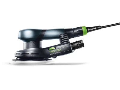
When the glue on the frame is dry, loosen the clamps and use an eccentric sander and P120 grit sandpaper to sand the connections smooth.
Use either a circular saw or a hand planer to bevel the upper edge of the frame.
-
Step 13
Lay all of the slats (position 9) for the lower shelf together. Pre-drill the four holes needed to fasten the first and last slats of the shelf slats. Screw both slats flush with the outer corners. Then, push all of the slats together and measure the distance to the outer slats.

-
Step 14
Divide this measurement by the number of spaces (7). In this way, you can obtain the exact gap measurement. Cut a strip to this length and when screwing down the slats, use this as a spacer block between the slats. You can work more efficiently if you place several slats with spacer blocks between them and then clamp, pre-drill and screw together.

-
Step 15
The upper slatted shelf is built in the same way. Here it is important that both of the outer slats are shifted inwards by one gap measurement. Drill 3.5 mm holes in the shelf support slats of the upper slatted shelf and screw the grill to the box.

-
Step 16
Use a jigsaw to cut round discs (position 16) from plywood to use as the adjustable feet. Deburr the edges with a hand-sanding block. On the underside of the discs, drill a 30 mm hole. The depth should correspond to the head of the machine screw (M10 x 80) and a flat washer.

-
Step 17
Next, drill a 10 mm through hole for the screws. On the opposite side, first place a flat washer and a nut. Tighten the nut using a ring spanner or an open-end spanner. Insert screw-in sockets or knock-in sockets as a counter-thread for the discs.

-
Step 18
The drill depth should correspond to the length of the machine screw. The drill diameter is dependent on the type of socket used and from which manufacturer. If you use knock-in sockets, which are easier to work with, you should drill through them twice after insertion and secure them against shifting with 3.5 x 35 SPAX screws.

-
Step 19
Drill the 8 mm holes into the closure (position 7) for the height adjustment of the lid. Countersink the holes thoroughly. Position the hinge on the upper narrow edge of the closure and line it up with the centre of the long edge, flush with the closing edge.

-
Step 20
Use an awl to pierce the screw holes and fasten with 3.5 x 25 mm SPAX screws. Attach them at a 50 mm distance from the corner and on the underside, ensure that both hinges are flush with the lid. Piercing the screw holes helps to position the screw in the centre of the fastening hole so that the hinge
does not shift to the side when it is being screwed in.
-
Step 21
Place the lid onto the shelf with the upper side facing downwards, ensure the sides are lined up flush with each other and secure tightly. Fasten the lid and join together with SPAX screws. Pre-drill 3.5 mm drill holes into the legs (positions 14 and 15) and screw the legs to the box.

-
Step 22
Screw the closure to the centre of the lid frame and use an 8 mm drill bit to drill the upper hole through to the interior of the box. Use a scraper or sandpaper to smooth the edges of the acrylic glass panel. Mark the drill holes onto the protective film and use a 3.5 mm wood drill bit with centring point to drill the holes.
Countersink the holes.
-
Step 23
Place plastic flat washers between the frame and pane when screwing together. Fasten a chain to the side of the box and under the lid. We have used an 8 mm aluminium tube as a closure (position 17). Cut it to 60 mm and on the end, drill a 4.5 mm hole so that a key ring with 30 mm diameter can be threaded through.

-
Step 24
This ring will be attached to a chain which is used to fix the aluminium tube onto the lid or the box. Dismantle the cold frame again and work on the surfaces using an eccentric sander, ending on a P180 grit sandpaper. Use a coloured glaze on the box and frame and a transparent one on the solid wood parts.


