


Stable, detachable and glued DOMINO dowelling joint
Description

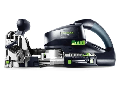
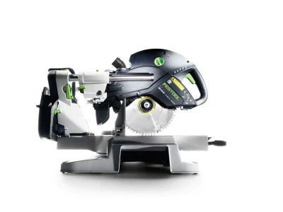
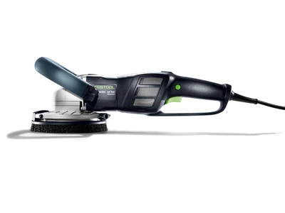
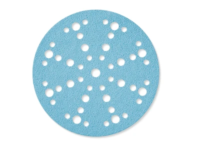
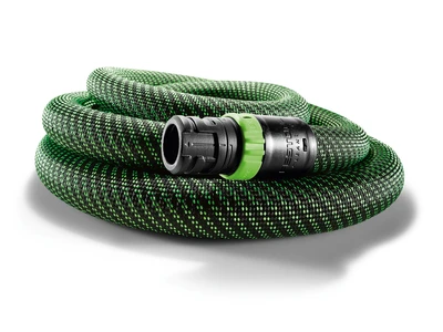
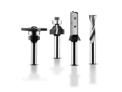
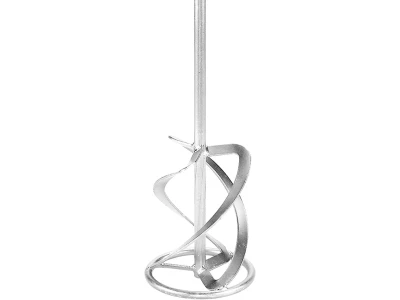
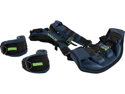
Tools/accessories
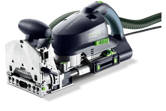


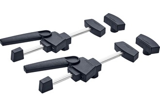


Alternative tools

Preparation/set-up
-
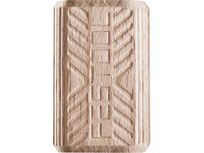
For detachable corner connectors, you will need the following components from the DOMINO corner and surface connector system:
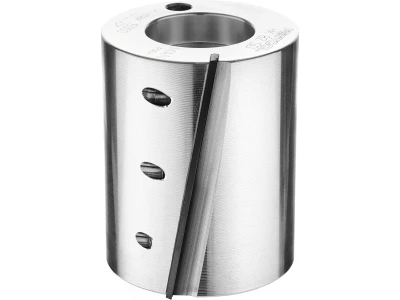
1. Anchor bolt
2. Split anchor with a self-drawing property – to hold it securely in the workpiece
3. Transverse anchor including stud
4. Dowel half-shells – clipped around double-headed or anchor bolts. Items included with double-headed and anchor bolts.
-
Measurements for routing the DOMINO corner connector:
All milling grooves are made in the narrow hole width.
Milling groove A: Routing depth 25 mm; Flap height approximately 1/2 workpiece thickness plus possible kickback
Milling groove B: Routing depth 50 mm; Flap height approximately 1/2 workpiece thickness
Milling groove C: Routing depth = x + minimum 10 mm (minimum 25 mm); Flap height 40 mm

-
Set the routing depth of the joining machine to 25 mm – set the markers to 25 mm and 50 mm.

-
For a dowelling joint, it is advisable to work using the stop pins. Select the pins depending on the desired hole distance. Ensure that the routing for the corner connector has a minimum distance of 37 mm from the edge of the workpiece. If you work with the stop pins, use the centre pin at least.


Procedure
-
Route DOMINO milling grooves in table legs or bedposts (narrow hole width), with a routing depth of 25 mm. One milling groove for the corner connector split anchor, the others for load transfer via conventional DOMINO dowels.

-
Change the routing depth to 50 mm and route the holes (narrow hole width) in the frame according to the scribe mark or using the stop pin system. The routing height is determined by the thickness of the individual material; as you are already used to with your DOMINO DF 700. In this example, the material thickness of the frame is 30 mm. Set the routing height to 15 mm, so that the routed hole is centred in the material.

-
For routing the transverse hole, now set the routing depth to 25 mm. (This measurement is dependent on each individual workpiece – see scale drawing. It is vital that the transverse hole overlaps the longitudinal hole by 3 mm in depth.)

-
The flip stop point, i.e. the routing height adjustment, must always be set to 40 mm. This ensures that the transverse hole always sits at the right distance from the edge of the workpiece and that the anchor bolt then catches the transverse anchor.

-
Now route the transverse hole into the frame where the connector is to be inserted. Flip the handle down at the front of the edge of the workpiece and align the machine at the scribe mark or using the stop pins (depending on how the horizontal routed hole was set).
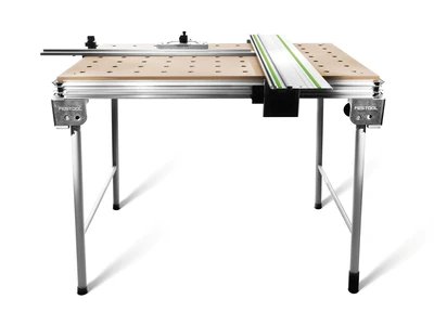
Tip: For a bigger and therefore safer support surface, it is possible and would be beneficial during this routing process to mount the support surface extension onto the DF 700.

-
Insert the expansion anchor into the centre of the routed holes in the table leg.

-
It is important to ensure that the expansion anchor is flush with the workpiece surface.

-
Then screw the anchor bolt all the way into the expansion bolt. This expands the expansion bolt, pulling it another approx. 1 mm into the workpiece thanks to the self-drawing property of the bolt and locking it securely into place. A 10 mm open ended spanner is used here.
Tip: Alternatively a 4 mm hex socket can be inserted through the hole or a ratchet with a 10 mm socket can be used.

-
Then unscrew the anchor just enough so that the countersink is facing the right direction. The split anchor now sits securely in the workpiece. It cannot fall out of the routed hole, even when the connection is detached again for transporting.

-
Clip the two dowel half-shells around the anchor bolt. These hold the corner connector firmly in the workpiece.

-
The transverse anchor is then inserted into the transverse hole in the side wall, with the screw hole facing upwards.

-
Using the Allen key, push the transverse anchor all the way into the routed hole.

-
Now insert the threaded screw. Tighten it only so far that the screw stays in place but the opening remains open for the anchor bolt.

-
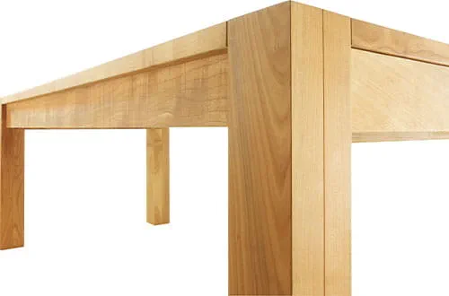
Then join the frame to the leg by pushing the connectors and dowels into their respective holes.

-
Tip: It is usually a good idea to fit flexible connectors to one of the sides and securely glue dowels into the other side.

-
Tighten the connection using a 4 mm hex key.

-
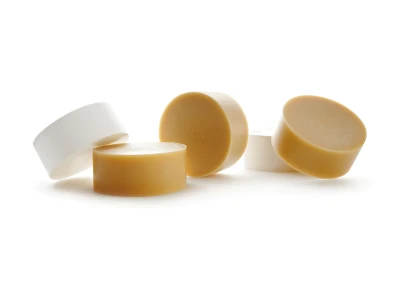
Optionally, you can cover the routing with a cover cap – available in one of three colours depending on the material: silver, light brown or dark brown.

-
This quickly creates a solid joint, without elaborate measuring or marking, which can be detached again quickly if required.


-
Our illustrated guides and work results are documented working steps that we have performed in practice. They are individual examples and do not guarantee or promise that users will obtain the same results. The results will depend on the user's experience and skill, as well as the material being used. Illustrated guides do not replace any Festool operating manuals and/or safety instructions. Liability for ensuring that the information, instructions and applications are free from content defects and defects of title, in particular with regard to the absence of defects, correctness, freedom from third party intellectual property rights and copyrights, completeness and fitness for purpose, is excluded. Claims for damages made by the user, regardless of their legal basis, are excluded. These liability exclusions are not applicable if the damage was intentional or caused by gross negligence, or in cases of statutory liability.
We cannot accept liability for damage resulting from defects.↑
