


How can parquet steps be created from floorboards?

Description
How I can create a neat step from floorboards, totally without angle rails, using the right tool.
Material list:
- Wood glue
- Mounting adhesive
- Adhesive tape
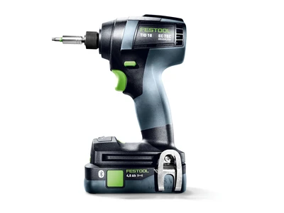
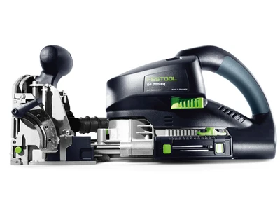
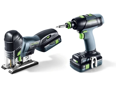
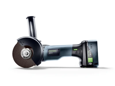
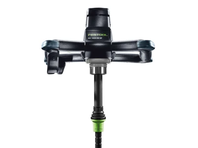
Tools/accessories


Alternative tools
The following tools and accessories are recommended as an alternative:


Preparation/set-up
-
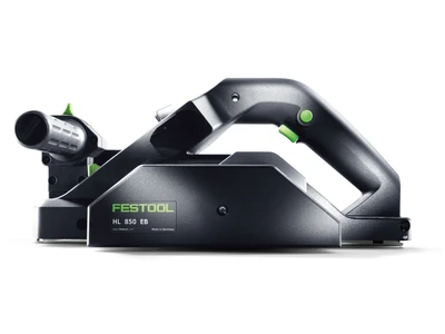
Creating a 46–47° edge
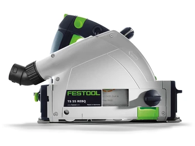
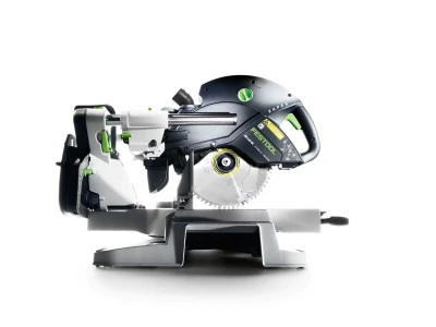
To achieve a clean edge, we must undercut the wood slightly. This can be done very easily on an already flat surface, as in this example. Using the plunge-cut saw and the over 45° cut setting.

-
Setting the plunge-cut saw correctly
First loosen the two rotary knobs and push the machine into the 45° angle. Then pull the green knob and set the angle to at least 46° and fasten both screws one after the other.


Procedure
-
Carrying out the angled cut
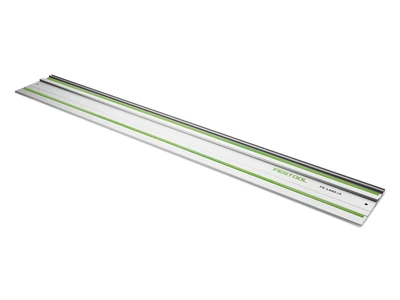
Then we place the guide rail on straight and place the plunge-cut saw on top, plunge and make a clean angled cut.

-
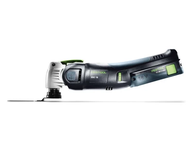
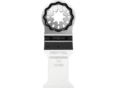
Trimming the corners
As we cannot cut right into the corner, we manage using the OSC 18 to adjust the rest of the area. To do this, we turn the guide rail round 180° with the solid aluminium side as a fence, in order not to ruin the splinter guard. Reduce the speed on the oscillator, use the angle of the existing cut when positioning and cut very carefully in the corner along the guide rail.

-
Hoovering afterwards

-
Cutting the counterpart
To create a perfect fit for the counterpart and for the sake of ease of cutting, we first cut an angle also of at least 46° from the riser using the CS50

-
Riser height
Then we measure the height of the riser

-
Riser cutting
Then we set the width of the riser with the stopper on the CS 50 scale and cut this lengthwise and trim it afterwards to the correct width.

-
Precision check
Possibly re-cut again

-
Checking again

-
Attaching adhesive tape
In order for the adhesive to stick securely and to fix the angle given, adhesive strips are positioned on the riser as support so that it can be attached to the counterpart cleanly when they are removed. See other pictures.

-
Surface bonding
Apply mounting adhesive to the surface

-
Gluing the mitre

-
Attaching adhesive strips
We now secure everything with the adhesive tape in order to create a good, clean seam

-
Adhesive strips along the entire length
Then leave to dry first

-
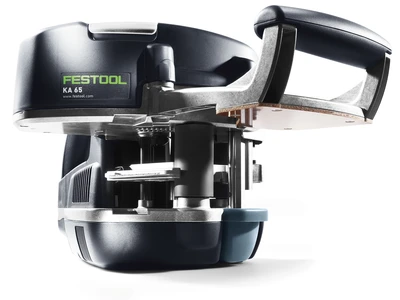
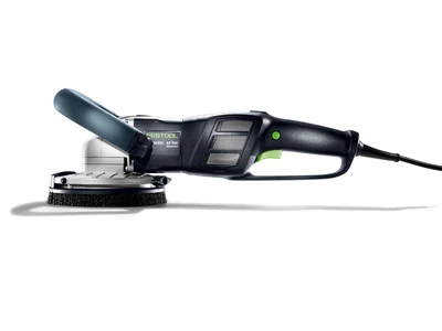
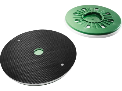
Setting the desired radius
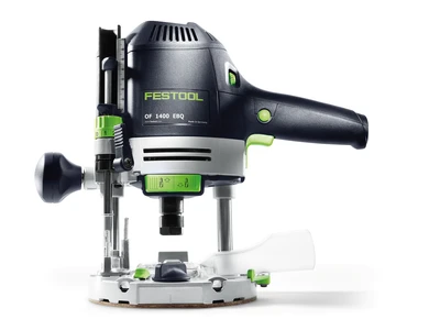
Set the desired router for the radius on the OFK 500, as described in the operating manual.

-
Setting the routing depth
Set the router to the appropriate depth, as described in the operating manual.

-
Guiding the router cleanly over the whole length
Switch on the router, place it carefully and evenly on the wood, then go slowly into the material and slide along the edge along the bearing guide.

-
End results
Now you have a very neatly created step.


-
Our illustrated guides and work results are documented working steps that we have performed in practice. They are individual examples and do not guarantee or promise that users will obtain the same results. The results will depend on the user's experience and skill, as well as the material being used. Illustrated guides do not replace any Festool operating manuals and/or safety instructions. Liability for ensuring that the information, instructions and applications are free from content defects and defects of title, in particular with regard to the absence of defects, correctness, freedom from third party intellectual property rights and copyrights, completeness and fitness for purpose, is excluded. Claims for damages made by the user, regardless of their legal basis, are excluded. These liability exclusions are not applicable if the damage was intentional or caused by gross negligence, or in cases of statutory liability.
We cannot accept liability for damage resulting from defects.↑
