


Building a wooden canopy yourself

Description
A wooden canopy protects the front entrance door and adds significantly to the character of a house. Depending on the design and shape of the roof canopy, creating one requires some basic knowledge of carpentry. This application example describes how to handle and use the machines. The required marking (marking out) of the processing steps is not contained in this application example.
Material list
- The material depends on the type of construction and is selected accordingly
- 10 x 10 cm cross-cuts are used for the basic structure
- 8 x 12 cm wood is used for the rafters
- 10 x 16 cm wood is used for the hip rafters
Tools/accessories


Preparation/set-up
-
Marking and laying out the wood for the basic structure
The wood for the threshold cornice and the two posts are marked according to the drawing and supported on trestles.

-
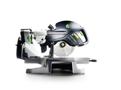
Preparing the portable circular saw
The HK 132 is used for cutting the wood. In order to use the guide rail later, the parallel side fence is fitted on the motor side and fully pushed up and attached to the machine table. In this position, the GC 1000-WA gauge marker can be used.

-
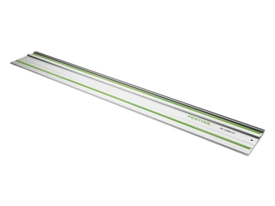
Placing the guide rail
The guide rail is fitted with the gauge marker and laid out.

-
The correct position for the guide rail is determined using the gauge marker. In this case, a cut at 0° should be produced. After it has been aligned, the rail can be fixed with clamps.


Procedure
-
Cutting using the HK 132
The portable circular saw is now guided precisely through the rail via the parallel side fence. The correct position can be checked on the machine gauge marker. The cutting depth is set to 12.5 cm.

-
Cutting using the HK 132
Make the cut and repeat the procedure for all 90° cuts required.

-
Flattening using the HK 132
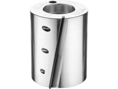
The threshold cornice wood should have laps (10 cm wide), as seen in the picture. To create these, the HK 132 is fitted with the flattening device. This allows flattening to a depth of 80 mm. The routing width is 50 mm. For wider flattening, the machine must be converted accordingly.

-
Aligning the guide rail
When using the flattening head on the HK 132, it is imperative that the machine is guided using a guide rail.
Tip: The GC 1000-WA angle stop is very well suited for aligning the rail precisely.
-
The routing process is performed in two steps, since per routing operation a maximum of 50 mm can be removed. The position for the first routing operation is therefore marked at 50 mm.

-
The position of the guide rail can now be aligned via the gauge marker and fixed accordingly.

-
Setting the flattening depth
The routing depth must be adjusted visually in advance of the milling groove. To do this, the flattening head is lowered until the planer blade meets the depth mark. Always disconnect the machine from the power supply when performing adjustments.

-
Completing the milling groove
The machine can now be hung in the guide rail via the parallel side fence and the milling groove can be made.

-
Tip:
To avoid splinters, chisel to the line in advance of the milling groove.

-
Carrying out the second routing operation
For the second routing operation, the guide rail is repositioned as per the previous steps and the milling groove is made. The process is repeated for any other flattening required.

-
The lap joint can be cleaned out using a mortise axe or a chisel as required.

-
Cutting rafters
The following steps describe how a bird's mouth notch should be cut in the rafters of the canopy. In order to do this, the wood is laid out and aligned to the markings.

-
The HK 132 is fitted with a bird's mouth notch head, as described in the operating instructions.

-
Setting the inclination
The inclination is set according to the roof inclination (here 30°).

-
Setting the bird's mouth notch depth
In order to set the appropriate bird's mouth notch depth, first refer to the table (on the motor). In this case, a bird's mouth notch at 30° roof inclination (Y-axis) and a bird's mouth notch depth of 25 mm (X-axis) should be cut. The setting depths can be read from the table. In this case, the depth is set at 85 mm.

-
Fitting the parallel side fence
It is imperative that a guide is secured for the milling groove. Later the guide rail will be used to guide via the fitted parallel side fence. If possible, the fence should be fitted on the right-hand side, in order for it to be supported better. The fence should be fitted at a distance of approximately 12–16 cm parallel to the machine table.

-
Side alignment of the milling machine
In the next step, the milling machine must be aligned so that the bird's mouth notch head pre-cutter blade is positioned at the bird's mouth sinker line.

-
Securing the guide rail
If the side position of the milling machine has been determined, the rail is fixed and is also fixed at the same distance on the opposite side.

-
Carrying out routing
After the guide rail has been fixed and the depth set accordingly, a milling groove can be made.

-
Cutting the rafter heads
The rafter heads are usually cut after the bird's mouth notches have been created, in order to ensure there is enough support for the machine and the guide. This can also be handled differently according to the situation. In this example, the rafter head should now be cut at an angle of 60°. The cut is made on the cut side of the wood. For this step, the guide rail is aligned to the 60° crack by means of the gauge marker and fixed accordingly. The gauge marker range is selected by which the parallel side fence on the saw blade side is fitted at a distance of 70 mm from the machine bench.

-
Setting the parallel side fence for cutting the cut side
The fence is fitted on the saw blade side at a distance of 70 mm and the machine can be guided safely. The aforementioned gauge marker range on the gauge marker can be used in this position.

-
Carrying out the angled cut
Note: The cut is carried out using the gauge marker correctly, in this case on the cut side ("saw blade to the left of the line")

-
Completing the eaves section of the rafters
In order to carry out a right-angled cut, the parallel side fence is fitted on the motor side again and, using the angle stop, the cut is carried out accordingly.

-
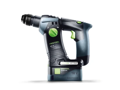
Drilling holes in the bird's mouth notch corner to secure the rafters
The holes for the necessary securing of the rafters are drilled after cutting the rafter heads using the cordless drill and a 7–8 mm auger drill bit.

-
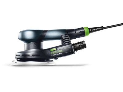
Sanding the rafter heads
It is recommended that the rafter heads and exposed surfaces are sanded directly after cutting. When joined together, there is an optimum and large support surface. A quick result can be achieved using the belt sander (80 and 100 grit).

-
Creating a mitre cut on the rafters
In this example, all rafters must have a mitre cut in order to lie comfortably in the hip rafters. These cuts are also created using the HK 132. To do this, all rafters are laid out, aligned and cut in one processing step using the GC 1000-WA angle stop.

-
Cutting the eaves cut on the hip rafters
The hip rafters must have two 45° cuts. To do this, all hip rafters are laid out, aligned and cut using the angle stop. First the angle is set at the angle stop and later aligned and fixed using the gauge marker.

-
To make the cut, the parallel side fence is fitted again on the saw blade side at a distance of 70 mm to the machine bench and the cut is made. Repeat the process then for any cuts required.

-
Creating other cuts
The horizontal eave cuts on the hip rafters and cutting the braces are carried out as previously described using the angle stop.

-
Deburring the hip rafters
In order to carry out the required deburring of the hip rafters (roof-shaped bevel on the upper surface), the appropriate machine angle is set on the portable circular saw and the deburring is carried out using the parallel side fence.

-
Creating a hip rafter bird's mouth notch
The hip rafter bird's mouth notches (heart milling) require several work steps. First the wood fibres are trimmed using a chisel, in order to prevent splintering later.

-
Creating a hip rafter bird's mouth notch
The horizontal bird's mouth cut can be carried out using the SSU 200 sword saw and a guide rail.

-
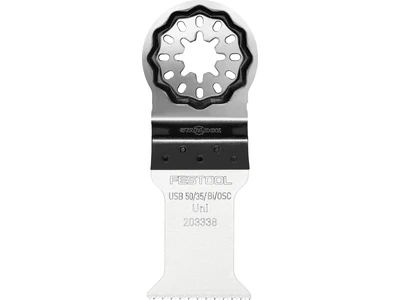
Creating a hip rafter bird's mouth notch
For the cuts in the rear area of the bird's mouth notch, the cordless oscillator is fitted with a long blade and the bird's mouth notch can be machined.

-
Sanding pre-cut wood
All wood can be sanded after cutting. A quick result can be achieved using the belt sander (80–100 grit)

-
All edges are now processed using the edge router. The 45° chamfer cutter is used in this case. The edge router is highly recommended when processing the rafter head area, as it cannot tip over through the small bench opening.

-
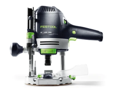
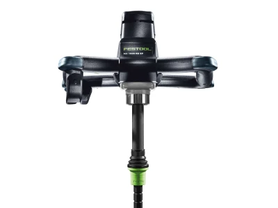
Joint between the posts and the threshold cornice
The Domino XL is used to join each post to the threshold wood. Two 14 x 100 mm dominoes are used for each to secure in position and to make fitting easier.

-
Joint between the posts and the threshold cornice
The first milling groove should be routed 30 mm from the edge. This can be read comfortably using the scale and the domino routing placed accordingly. Attention: Set the associated routing depth.

-
Joint between the posts and the threshold cornice
The position of the second milling groove is set using the stop pins. In this case, the first pin is used. The process is repeated for the sills and posts.

-
Joint between the braces and the sills
In order to place two domino dowels, first the brace must be brought into the correct position and then two axis markings made. Here the dowels are then routed into the brace and the post.

-
Joint between the braces and the sills
The Domino router is positioned on the axis markings and the two milling grooves are routed.

-
Joint between the braces and the sills
The appropriate milling grooves are made and the joint (securing in position) of the two components is created.

-
Assembly
Once all dowelling joints have been created, the required screws can be inserted using a cordless drill or cordless impact screwdriver. It is recommended that a test assembly be performed before the final assembly of the canopy.

-
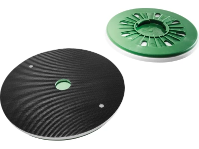
Sanding the structure
It may be necessary to sand the transitions too. This sanding can be completed quickly using the ROTEX. Using the coarse sanding function, a high material removal rate can be achieved, which can be very useful when sanding the end grain. After coarse sanding, switch to the sanding function, in order to achieve an optimum surface result.

-
Assembly
For the assembly, first the posts are fixed to the already assembled braces. For the final assembly, appropriate fasteners must be selected depending on the substrate. It may then be necessary to drill additional holes. Then the threshold cornice wood abutting the wall can be inserted and secured. The Domino dowel makes assembly easier and the joint fits straight away.

-
Assembly
Then the remainder of the threshold wood can be assembled. Sometimes the rafters can be pre-assembled and the whole assembly can simply be mounted and appropriately fixed.

-
Assembly
Attach the remaining jack rafters using appropriate screws. This can be carried out comfortably and without kickback using the cordless impact screwdriver.

-
Final sanding
A cordless sander is perfect for smaller sanding jobs after assembly at the destination. Here the cordless Delta sander is used to sand off small dirty spots or smudges, marks or other imperfections.

-
End results
The result is a self-built wooden canopy. Creating it is simple with the right tool. After cutting and a test assembly, nothing stands in the way of assembly at the destination.


-
Our illustrated guides and work results are documented working steps that we have performed in practice. They are individual examples and do not guarantee or promise that users will obtain the same results. The results will depend on the user's experience and skill, as well as the material being used. Illustrated guides do not replace any Festool operating manuals and/or safety instructions. Liability for ensuring that the information, instructions and applications are free from content defects and defects of title, in particular with regard to the absence of defects, correctness, freedom from third party intellectual property rights and copyrights, completeness and fitness for purpose, is excluded. Claims for damages made by the user, regardless of their legal basis, are excluded. These liability exclusions are not applicable if the damage was intentional or caused by gross negligence, or in cases of statutory liability.
We cannot accept liability for damage resulting from defects.↑
